
Radio Protocol Architecture
The 5G NR radio access network is comprised of these protocol entities:
- Service data adaptation protocol (SDAP)
- Packet data convergence protocol (PDCP)
- Radio link control (RLC)
- Medium access control (MAC)
- Physical layer (PHY)
To meet the desired key capabilities of 5G NR, the other layers of the stack provide various enhancements over their LTE counterparts. The PDCP, RLC, and MAC protocols handle tasks such as header compression, ciphering, segmentation and concatenation, and multiplexing and de-multiplexing. PHY handles coding and decoding, modulation and demodulation, and antenna mapping.
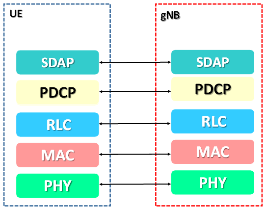
USER Plane: The figure below shows the protocol stack for the user plane, where SDAP, PDCP, RLC and MAC sublayers (terminated in gNB on the network side)
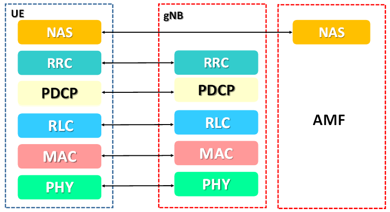
Control Plane :
The figure below shows the protocol stack for the control plane, where:
- PDCP, RLC and MAC sublayers (terminated in gNB on the network side)
- RRC (terminated in gNB on the network side)
- NAS control protocol (terminated in AMF on the network side) performs the functions listed in TS 23.501,for instance: authentication, mobility management, security control…
SDAP: The service data adaptation protocol is a new sublayer in layer 2 which immediately interfaces with the network layer and provides a mapping between the QoS flows and data radio bearers (DRBs). It also marks the QoS flow identifiers (QFIs) in the downlink and uplink packets. A single-protocol entity of SDAP is configured for each individual PDU Session. SDAP applies also to LTE when connected to the 5G Core. The introduction of SDAP enables end-to-end QoS framework that works in both directions.
PDCP: PDCP sublayer processes the radio bearers and maps them in a one-to-one manner to RLC channels (i.e. a single radio bearer corresponds to a single RLC channel), The PDCP layer also handles Robust Header Compression (ROHC) and security for the data packets.
RLC: RLC sublayer processes RLC channels and maps them in a one-to-one manner to logical channels (i.e. a single RLC channel corresponds to a single logical channel, segmentation and Automatic Repeat Request (ARQ) functionality are man function.
MAC: MAC sublayer processes logical channels and maps them to transport channels in a many-to-one manner (i.e. multiple logical channels can be mapped to a single transport channel), eg. Scheduling, multiplexing,HARQ( Hybrid Automatic request.)
PHY: PHY layer processes transport channels and maps them to physical channels in a one-to-one manner (i.e. a single transport channel is mapped onto a single physical channel), coding, decoding.
Comments
Comments are closed.