
Main pillar of the NR is a Synchronization Signal and PBCH block (SS/PBCH block).
SSB Block contains
- PSS 2 SSS PBCH
In this article , I am going to discuss about PSS.
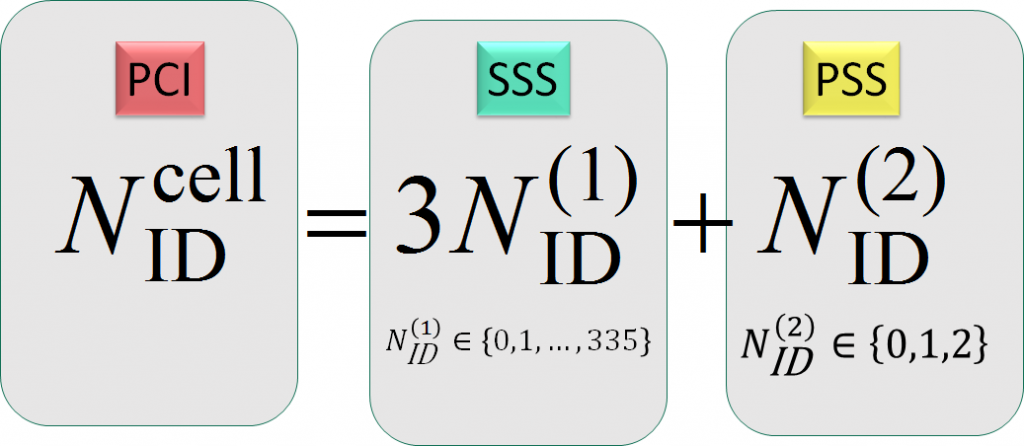
Lets see the PCI formula below.
Lets first understand LTE PSS location in sub frame.
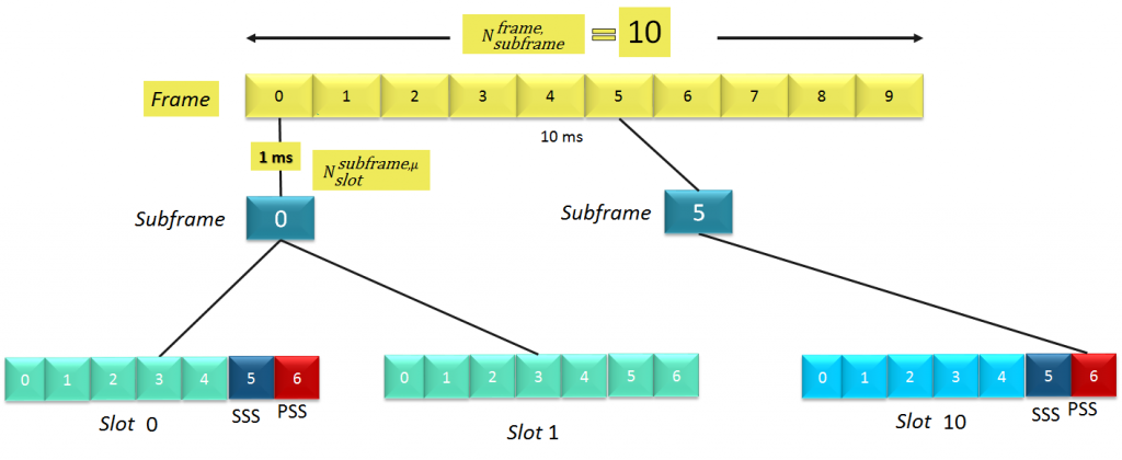
For FDD frame, PSS is allocated on symbol 6 (last symbol) of slot 0 (subframe 0) and slot 10 (subframe 5) of each radio frame.
And, for TDD frame, PSS is allocated on symbol 2 of slot 2, subframe1 and slot 12 subframe 6 of each radio frame.
NR PSS is also same like LTE PSS, where we use as Physical layer reference signal, this we use to get radio frame boundary for device & to detect the cell ID sector N(2,ID)
Instead of using Zadoff-Chu sequences as in LTE,
NR adopted a frequency domain based BPSK M-sequence. M-sequence was selected because of not having time offset – frequency offset ambiguity present with Zadoff-Chu sequences.
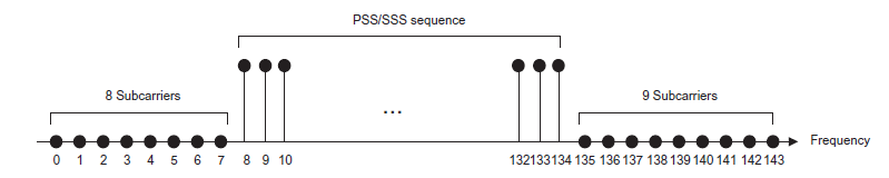
LTE PSS consist of one of three 62 symbols zadoff chu sequence and is mapped to the central 72 subcarriers with a guard band of 10 subcarriers.
| 5G NR PSS Consist of one of three 127 symbols m-sequence |
| 5G NR PSS is allocated on the first symbol of each SSB |
Similar to LTE, NR also have 3 PSS sequence ,
The 3 possible m-sequences for the PSS are defined as follows
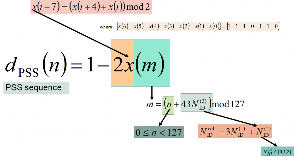
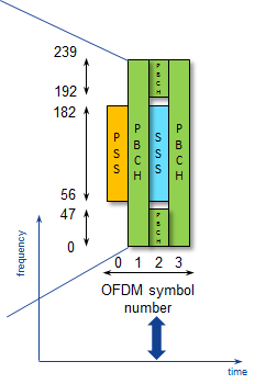
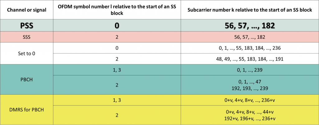
Mapping of PSS within an SS/PBCH block
The UE shall assume the sequence of symbols dpss(0) …………….dpss(126) constituting the primary synchronization signal to be scaled by a factor to conform to the Bpss power allocation and mapped to resource elements(k,l) in increasing order of k where K & L and which represent the frequency and time indices, respectively, within one SS/PBCH block.


Comments
Comments are closed.