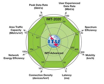
From IMT Advanced to IMT 2020
| Performance measure | Requirement |
|---|---|
| Peak data rate | DL: [20 Gbps] UL: [10 Gbps] |
| Peak spectral efficiency | DL: [30 bps/Hz] UL: [15 bps/Hz] |
| Spectrum Scalability | Yes |
| Bandwidth | Reference to IMT-2020 |
| Bandwidth Scalability | Yes |
| Control plane latency | [10 ms] |
| UP latency URLLC, one-way | [0,5 ms] |
| UP latency eMBB, one way | [4ms] |
| Latency for infrequent small packets | 10s / 20byte packet |
| Mobility interruption time (intra-syst.) | [0 ms] |
| Mobility | Up to 500 km/h |
| Inter-system mobility | Yes |
| Reliability | [1-10-5] in [1ms] |
| Performance measure | Requirement |
|---|---|
| UE Battery life | 10-15 years |
| UE energy efficiency | Inspection (Qualitative) |
| Cell/Tx Point/TRP sp. Eff. | 3xIMT-A requirement |
| Area traffic capacity | 10Mbps/m2 [ITU] |
| TRP spectral efficiency | [3x IMT-A requirement] |
| User experienced data rate | 100/50 Mbps DL/UL [ITU] |
| User sp. eff. at 5% percentile | [3x cell edge IMT-A requirement] |
| Connection density | [1,000,000 devices/Km2] |
| NW energy efficiency | Qualitative & Quantitative KPI |
| eMBB Extreme coverage | 140/143 dB loss MaxCL (2/1(DL)) |
| IoT Coverage | MCL [164dB] for [160bps] |
| Support of wide range of services | Yes |
Selected KPIs, high-level assessment method and scenario.
| KPI | Units | Method | use cases |
|---|---|---|---|
| Bandwidth | Hz | Inspection | Generic |
| Peak data rate | bit/s | Analysis | eMBB |
| Peak SE | bit/s/Hz | Analysis | eMBB |
| UP latency | ms | Analysis | URLLC, eMBB |
| CP latency | ms | Analysis | URLLC, eMBB |
| Energy efficiency | % | Analysis | mMTC, eMBB |
| 5th perc. user SE | bit/s/Hz | System-level | eMBB |
| User exp. data rate | bit/s | System-level | eMBB |
| Average SE | bit/s/Hz | System-level | eMBB |
| Area traffic capacity | bit/s/m2 | System-level | eMBB |
| Mobility | km/h | System-level | URLLC, eMBB |
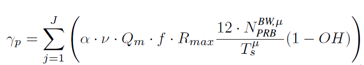
# Peak data rate
Peak data rate is the highest theoretical data rate which is the received data bits assuming error-free conditions assignable to a single mobile station, when all assignable radio resources for the corresponding link direction are utilized (i.e., excluding radio resources that are used for physical layer synchronization, reference signals or pilots, guard bands and guard times).
The peak data rate in NR can be calculated as follows.
# Peak Spectral efficiency
Peak spectral efficiency is the highest theoretical data rate (normalized by bandwidth), which is the received data bits assuming error-free conditions assignable to a single mobile station, when all assignable radio resources for the corresponding link direction are utilized (i.e., excluding radio resources that are used for physical layer synchronization, reference signals or pilots, guard bands and guard times).
Higher frequency bands could have higher bandwidth but lower spectral efficiency and lower frequency bands could have lower bandwidth but higher spectral efficiency. Thus, the peak data rate cannot be directly derived from peak spectral efficiency and bandwidth multiplication.
# Bandwidth
Bandwidth means the maximal aggregated total system bandwidth. It may be supported by single or multiple RF carriers.
The maximum supported bandwidth may be composed of either a single or
multiple radio frequency (RF) carriers. It is calculated by inspection.
The IMT-2020 minimum requirement is 100 MHz in FR1 (410 MHz – 7.125 GHz) and 1 GHz in FR2 (24.25 GHz – 52.6 GHz)
# Control plane latency
Control plane latency refers to the time to move from a battery efficient state (e.g., IDLE) to start of continuous data transfer (e.g., ACTIVE).
The target for control plane latency should be 10ms.
# User plane latency
The time it takes to successfully deliver an application layer packet/message from the radio protocol layer 2/3 SDU ingress point to the radio protocol layer 2/3 SDU egress point via the radio interface in both uplink and downlink directions, where neither device nor Base Station reception is restricted by DRX.
For URLLC, the target for user plane latency should be 0.5ms for UL, and 0.5ms for DL. Furthermore, if possible, the latency should also be low enough to support the use of the next generation access technologies as a wireless transport technology that can be used within the next generation access architecture.
For eMBB, the target for user plane latency should be 4ms for UL, and 4ms for DL.
# Latency for infrequent small packets
For infrequent application layer small packet/message transfer, the time it takes to successfully deliver an application layer packet/message from the radio protocol layer 2/3 SDU ingress point at the mobile device to the radio protocol layer 2/3 SDU egress point in the RAN, when the mobile device starts from its most “battery efficient” state. For the definition above, the latency shall be no worse than 10 seconds on the uplink for a 20 byte application packet (with uncompressed IP header corresponding to 105 bytes physical layer) measured at the maximum coupling loss (MaxCL) of 164dB.
#Mobility interruption time
Mobility interruption time means the shortest time duration supported by the system during which a user terminal cannot exchange user plane packets with any base station during transitions.
The target for mobility interruption time should be 0ms.
This KPI is for both intra-frequency and inter-frequency mobility for intra-NR mobility.
Mobility support can be relaxed for extreme rural scenarios for the Provision of minimal services for very low-ARPU areas: Inter RAT mobility functions can be removed. Intra-RAT mobility functions can be simplified if it helps decreasing the cost of infrastructure and devices. Basic idle mode mobility shall be supported as a minimum.
# Inter-system mobility
Inter-system mobility refers to the ability to support mobility between the IMT-2020 system and at least one IMT system
# Reliability
Reliability can be evaluated by the success probability of transmitting X bytes within a certain delay, which is the time it takes to deliver a small data packet from the radio protocol layer 2/3 SDU ingress point to the radio protocol layer 2/3 SDU egress point of the radio interface, at a certain channel quality (e.g., coverage-edge).
A general URLLC reliability requirement for one transmission of a packet is 1-10-5 for 32 bytes with a user plane latency of 1ms.
For eV2X, for communication availability and resilience and user plane latency of delivery of a packet of size 300 bytes, the requirements are as follows:
Reliability = 1-10-5, and user plane latency = 3-10 msec, for direct communication via sidelink and communication range of (e.g., a few meters)
– Reliability = 1-10-5, and user plane latency = 3-10 msec, when the packet is relayed via BS.
Note that target communication range and reliability requirement is dependent of deployment and operation scenario (e.g., the average inter-vehicle speed).
Link level evaluation with deployment scenario specific operating point and system level simulation are to be performed for the evaluations of Indoor Hotspot, Urban Macro, Highway, and Urban grid for connected car.
# Coverage
MaxCL in uplink and downlink between device and Base Station site (antenna connector(s)) for a data rate of 160bps, where the data rate is observed at the egress/ingress point of the radio protocol stack in uplink and downlink.
The target for coverage should be 164dB.
# Extreme Coverage
The coupling loss is defined as the total long-term channel loss over the link between the UE antenna ports and the eNode B antenna ports, and includes in practice antenna gains, path loss, shadowing, body loss, etc.
The MaxCL is the limit value of the coupling loss at which the service can be delivered, and therefore defines the coverage of the service.
The MaxCL is independent of the carrier frequency. It is defined in the UL and DL as:
– UL MaxCL = UL Max Tx power – eNB Sensitivity
– DL MaxCL = DL Max Tx power – UE Sensitivity
# UE battery life
UE battery life can be evaluated by the battery life of the UE without recharge. For mMTC, UE battery life in extreme coverage shall be based on the activity of mobile originated data transfer consisting of 200bytes UL per day followed by 20bytes DL from MaxCL of 164dB, assuming a stored energy capacity of 5Wh.
The target for UE battery life for mMTC should be beyond 10 years, 15 years is desirable
# UE energy efficiency
UE energy efficiency means the capability of a UE to sustain much better mobile broadband data rate while minimizing the UE modem energy consumption
# User experienced data rate
User experienced data rate NOTE1 can be evaluated for non-full buffer traffic and for full buffer traffic.
# Connection density
Connection density refers to a total number of devices fulfilling a target QoS per unit area (per km2), where the target QoS is to ensure a system packet drop rate less than 1% under given packet arrival rate l and packet size S.
Packet drop rate = (Number of packet in outage) / (number of generated packets),
where a packet is in outage if this packet failed to be successfully received by destination receiver beyond packet dropping timer.
The target for connection density should be 1 000 000 device/km2 in urban environment. 3GPP should develop standards with means of high connection efficiency (measured as supported number of devices per TRxP per unit frequency resource) to achieve the desired connection density.
REQUIREMENT COMPARISON IMT 2020 VS IMT ADVANCED
| ITU-R IMT-2020 | ITU-R IMT-Advanced | 3GPP LTE-A Pro | 3GPP New radio (NR) | |
| Bandwidth | Up to 1GHz | Up to 100 MHz | Up to 640MHz | Up to 1 GHz |
| Peak data rate | DL 20 Gbps UL 10 Gbps | DL 1.5 Gbps UL 0.675 Gbps | DL 3 Gbps UL 1.5 Gbps | DL 20 Gbps UL 10 Gbps |
| Peak spectral efficiency | DL 30 bit/s/Hz UL 15 bit/s/Hz | DL 15 bit/s/Hz UL 6.75 bit/s/Hz | DL 30 bps/Hz UL 15 bps/Hz | DL 30 bit/s/Hz UL 15 bit/s/Hz |
| User plane latency | Max: 4 ms | Max: 10 ms | Max: 2ms | Max: 0.5 ms |
| Control plane latency | Max: 20 ms | Max: 100 ms | Max: 50 ms | Max: 10 ms |
| Connection density | 1 000 000 devices/km2 | N/A | N/A | N/A |